Eagle Ground Plane
Now if you click on the blue ground trace below the label gr on the pc board, a box will pop up with the info about that circuit element. I had to push ratsnest to see the ground plane.

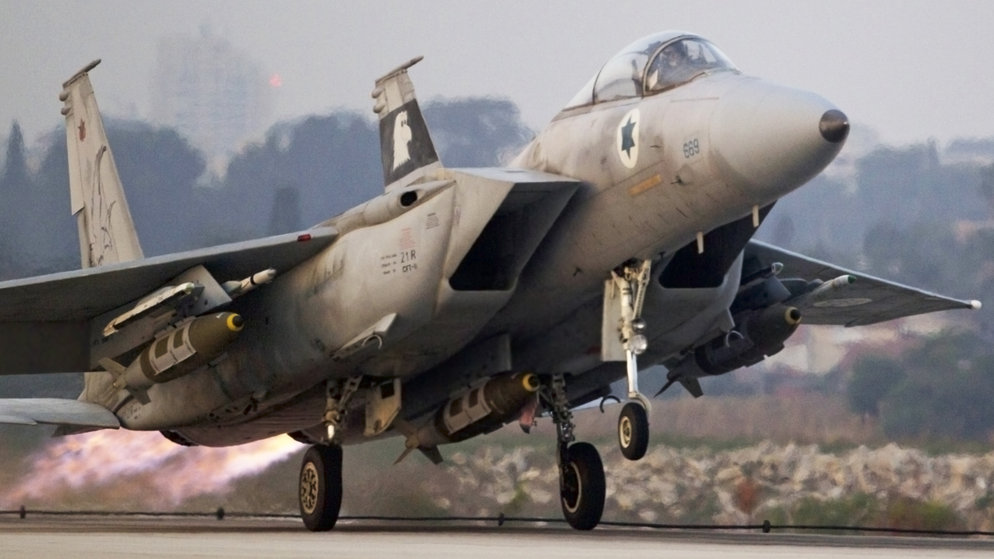
Israeli F15 Eagle HD Wallpaper Background Image
Note that the ground trace is named s1.
Eagle ground plane. This really is no different to when you have a signal on layer 1. Through hole components connect fine, and thermal bridges appear as expected, but when i route from the pad to a via, then select the ground plane, eagle doesn't recognise the connection, and the airwires remain. The ground plane is now updated with the new isolation value.
Hey, i'm having some trouble getting eagle to connect smt pads to the internal ground plane below them. I've followed the layout in the datasheet, placing a large copper polygon under the chip with solder mask over it, and in the center an smt pad to give me the necessary exposed copper and solder paste. Plane created by the ratsnet.
I have a package which i need to heat sink. Where the cadsoft eagle community meets. Gain additional flight proficiency, earn income, and qualify for lower insurance premiums.
When setting my ground plane using the poly tool as i'm used to i use all the standard settings, solid pour, thermals on, orphans off. In order to do this i close the file and then. The ground plane is now created.
If i export gerber file right after opening a design, while the ground plane is not displayed, i do get the right results. Lots of small islands are better than a few big ones. Im using the new eagle 5.4 for the first time.
In the properties window select an isolation value from the dropdown box and click ok. In other words i am unable to hide the ground. As a ground plane under rf lines like microstripe or coplanar lines.
If your ground plane is on layer 2 and the via is called gnd then the ground plane on layer 2 will connect to the via. You must have a line width greater than 0.00. Web access to cadsoft support forums at www.eaglecentral.ca.
The 5 day course offers the student a well organized, professional training experience. To add more isolation space between traces and the ground plane click on the info tool. Please tell me how can i hide the ground planes without.
I made a ground plane on the top layer, named it gnd, same name as the gound net on schematics. Six simple steps to creating ground planes with a polygon pour in eagle. Liuzengqiang january 31, 2011, 7:07am #1.
Go to the top menu bar in eagle and select view, then info from the dropdown list. For some reason the traces connecting to gnd pins are very tiny. Guide will explain how to create and connect to vias and ground planes using eagle additional help:
It can also reduce electrical noise on the board. Yet the plygon won't connect to the gound pins. When you pour a copper ground plane (or any signal pour), you can't draw the polygon with an outline at zero width.
Unfortunately eagle tends to clump vias, even with the hugging parameter set to 0. Try changing the line width of the polygon that defined the pour to as large as you can accept. The next step is to place a bunch of vias in the pad and copper region, but there doesn't seem to be a via tool in.
Ive been using 4.3 forever till now. Filling the board with a ground plane is the first thing we do when designing a pcb. I did some pcbs with eagle, so i was quite sure i know it's basics, especially when it comes to ground and power planes.
I cant figure out why. The info should be as shown in this example. As a power plane (for example vcc) and/or groundplane, to create a low resistance connections.
Generally to make a low resistance connection for tracks that carry a high current. The measure of a ground plane is how small the maximum dimension is of any island. This means you want the ground plane to flow around every via if possible.
To define a valid polygon in eagle you must follow some rules: The ground plane connects all the ground pins on a pcb automatically, which usually makes routing easier. Click twice on a side of the polygon.
In eagle, i always find the ground plane that i had is not displaying after i close a design and reopen it. Give it the same name as the ground connections on your schematic, usually "gnd" Ground plane vias are placed on the pcb to provide a stronger ground connection between the top and bottom ground layers and to prevent intersecting connections.
The smaller the width, the larger the gerber file.

Free Images wing, ground, airplane, plane, tarmac

US airman relaxes in Strike Eagle fighter jet at it flies
2001 Operation Noble Eagle > Air Force Historical

Cessna 421C Golden Eagle aircraft picture Cessna

Army focuses on power, propulsion for future unmanned

This is F15E Strike Eagle, the F15E is a multirole
American Eagle Flying, We'll Do Ground Handling
Fighter Jets Free Stock Photo An F15E fighter jet on

Federation of American Scientists F15 Eagle Air

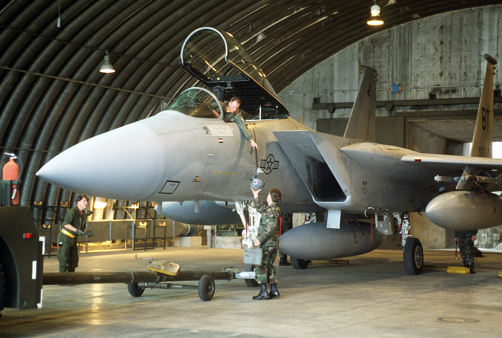
Ground crew members assist the pilot of an F15C Eagle

McDonnell Douglas F15 Eagle HD Wallpaper Background

Pin by Michael McGlauflin on جنگنده های جدید Fighter

Wallpaper airplane, military aircraft, air force
Pentagon awards Northrop Grumman stealth bomber contract

Images Gratuites sol, avion, macadam, militaire, jet


